Unfortunately, to avoid long lists of possible alternatives, we need a general term to refer to the local radio-frequency (RF) reference or 'RF common' - which is usually the chassis of an electronic product, a chassis supporting a number of printed circuit boards or modules or units; or the metal walls of the product's enclosure. Although such metalwork is often connected to the protective conductor I will use the term 'local RF reference' (where many might expect to see the possibly misleading word 'earth') and hope that this helps to avoid confusion between the safety and EMC functions of the above metalwork.
3.4 Communications within a company
Many companies have problems in turning the intentions of their designers into the constructions of their assembly staff. Nowhere is this more evident than in EMC, where apparently small variations in cable length or route, or component placement, can make huge differences. Whereas in serial manufacture there is (hopefully) time allowed for what is constructed to be compared with what was designed and any differences iterated out, in custom engineering designs need to be translated into products and systems without errors at the first attempt if a company is to maximise its profits and be successful. So it is important - to save time and money - that companies find ways to communicate the EMC assembly techniques that their designers have chosen to their assembly staff.
3.5 Following good EMC practices
Good EMC practices in the construction of electrical and electronic assemblies have been known for at least 10 years, and are continually evolving as the frequencies in common use increase. Relevant standards and public-domain documents include references [2] to [5], and there are a number of guides to good practices produced by companies which sell industrial components, such as [6] to [9].
Good EMC practices are often different from traditional practices, and in some long-established industries large amounts of money and time are still needlessly wasted by fixing EMC problems with systems and installations in the field instead of by design, because of a reluctance to learn about EMC or modern techniques. It often seems to be that the field problems aren't even recognised as being EMC-related.
Part of good EMC practice is to follow the EMC instructions provided by the manufacturers of the electronic units that are to be used - but only where these are reasonable and don't conflict with what is written in this series, or with each other. Where manufacturers' instructions differ or conflict, EMC expertise is needed. For example, some component manufacturers still specify that screened cables should have their screens bonded to 'earth' (meaning local RF reference) at one end only. While this is sometimes still acceptable, the number of instances in which it allows products to pass EMC tests are now very small. Such instructions are sometimes written by companies who have done no EMC testing, or tested using unrealistic set-ups, but who believe that it is best-practice and so slavishly repeat it in their manuals.
However, a thoughtful manufacturer could have filtered his product's low-frequency inputs and outputs so well that screened cables are not required for good radio-frequency (RF) performance, in which case bonding their cable screens at one end only could be acceptable as long as the cables don't interconnect two screened enclosures. Refer to sections 2.5 and 2.5.3 (in Part 2 of this series) and 3.8 below for more detail on this topic.
In general, good EMC procedures in design and assembly of assemblies require:
- Assessing the intended operational environment for its EM disturbances (threats to the new product).
- Assessing the intended operational situation for the sensitivity of other electronic equipment that might be present to the EM disturbances emitted by the new product (threats from the new product).
- Choosing electronics known to have the EMC performance required to meet specifications derived from the above steps.
- Following the electronics' manufacturers reasonable EMC instructions.
- Using the EMC techniques described below (and elsewhere in this series) everywhere else.
3.6 Creating a local RF reference
At frequencies above a few MHz, only an unbroken metal area or volume can achieve a reliable local RF reference, and only then for cables and electronics which remain within its boundaries. In the case of a metal sheet used as a local RF reference, the cables and electronics should remain close to its surface at all times. As a rule of thumb their height above the sheet should be less than one-twentieth of a wavelength at the highest frequency of concern (e.g. closer than 75mm at 200MHz, a typical walkie-talkie transmitting frequency).Where a metal chassis (ideally free from joints and perforations), metal cabinet, or metal enclosure is used the walls, rear, top, bottom, or door could be used as local RF references. Industrial cabinets often mount their electrical and electronic and other units on a metal backplate, or in a frame or cage for plug-in modules or printed-circuit cards. The metal support structures nearest to the electronics, such as backplates or card cages, should always form part of their local RF references and have multiple bonds to other nearby metalwork. Green/yellow wires to a star point will generally be ineffective at providing an RF reference ('earth') at frequencies above a few hundred kHz, and even where electronic units (such as low-frequency analogue processing) do not employ or emit RF frequencies, unless its manufacturer has taken great care it will happily demodulate any RF in their environment (and there is a lot of it about, these days). So even analogue electronics need EMC-wise assembly techniques too. Refer to [11] for more on the RF susceptibility of audio electronics, and by implication all low-frequency analogue signal processing such as instrumentation.
It is easiest to use metal structures as local RF references if they are finished with a durable and corrosion-resistant conductive coating. This is because only metal surface-to-metal surface bonds have any chance of working effectively at the highest frequencies in common use today. Non-conductive paint, plastic coatings, or anodising, all increase the inductance of bonds and reduce their effectiveness at high frequencies. Where painted or plastic-coated surfaces are to be bonded to, care must be taken to achieve a good bond at RF (usually involving local removal of paint or plastic), and then to prevent the corrosion that can occur because the protective coating has been removed.
In the case of industrial cabinets fitted with backplates, zinc-plated backplates have become the standard for almost all cabinet manufacturers in recent years, to help with RF bonding and EMC. Heavy zinc or tin plating is the best conductive finish for mild steel, but sometimes thinner plating is used with an additional passivation layer. Unfortunately, passivation is just a thin plastic coating and can ruin RF bonding properties. I am led to understand that 'yellow' passivation is easily punctured by modest pressure from metal parts such as the nuts and bolts typically used in electronic assembly, but would still prefer heavier plating and no passivation.
3.7 Bonding methods to optimise RF performance
3.7.1 Protective bonding (safety) conductor connections
Figure 3A shows the connection of the incoming protective conductor (often called the protective or safety earth, the green or green/yellow conductor in the mains supply cable) to the wall of an enclosure. Although this is primarily a safety concern (which is why we bond it to the external metalwork), it helps to achieve the best EMC performance from the enclosure if the amount of protective conductor exposed within the enclosure is 150mm or less. Bonding it to the outside of the metal enclosure would be best, but for safety reasons it needs to be closely associated with the mains terminals. Its bonding terminal is preferably welded to the enclosure side or rear, although it could be screwed. For safety reasons the best type of welded stud is one that penetrates the enclosure from the other side, so that if the weld fails it is still retained in place and doesn't just pull free.
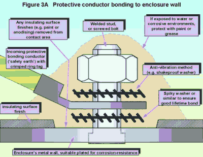
For industrial cabinets, the safety standard EN 60204-1 requires no more than one protective conductor per terminal (a requirement which appears to be widely ignored, making many industrial cabinets non-compliant with safety regulations). So to bond the backplate to the protective conductor requires a separate welded or screwed stud terminal near to the incoming 'safety earth' terminal (plus a sufficient cross-sectional area of metal between the two). Some control panel builders instead use a solid metal terminal block bonded reliably to the enclosure wall as their 'safety earth' star point.
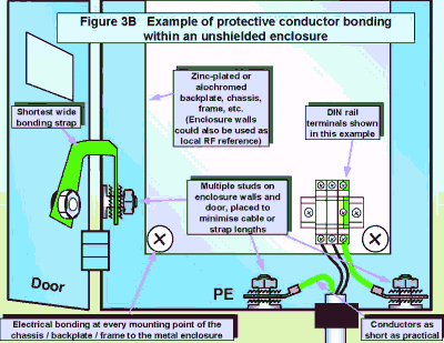
Doors and removable panels should have their protective bonding made to their nearest enclosure walls using their own studs and short wide straps or braids. In general, the shorter the length of strap or braid, the higher the frequency at which a metal enclosure provides some shielding benefits. At frequencies for which the longest enclosure dimension exceeds one-twentieth of the wavelength (depending on the shielding effectiveness required) such straps or braids provide few EMC benefits, no matter how short they are, and a shielded enclosure using conductive gaskets around doors and removable panels may be required instead (see 3.10).
Figure 3B is an example of protective bonding in a typical industrial cabinet fitted with a backplate. To help create a larger local RF reference area and get the benefit of whatever shielding is available from a basic enclosure, the backplate should be electrically bonded to the metal cabinet at every one of its fixing points.
3.7.2 Short wires or braided straps to the local RF reference
This assembly method is shown by Figure 3C and is very similar to 3.7.1 above. It is used when connecting internal protective bonding conductors, the pigtails of screened cables (but see 3.7.7), and other 'earth' wires to their local RF reference.
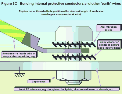
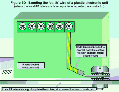
A captive nut or threaded hole is often used, making assembly easier than nut-and-bolt assembly. Sometimes self-tapping screws are used into a pilot hole, although check that these are acceptable if the bond has any safety purpose. The bonding point should be positioned so that the shortest length of wire or braid may be used. Even so, just a few inches of wire or braid can be completely ineffective (or even counter-productive) at frequencies of above a few MHz, as shown by some graphs in [4]. For plastic-bodied electronic units, their protective conductor terminal should be bonded to the nearest possible point on the local RF reference with the shortest wire of largest cross-sectional area, as sketched by Figure 3D.
3.7.3 Bonding metal bodies to the local RF reference
Direct metal surface-to-metal surface bonds give the best performance at higher frequencies, and should be used to bond all the metal fixings on any electronic units to their local RF reference as shown by Figures 3E and 3F.


3.7.4 Using the local RF reference as a protective bonding conductor
It is often possible to use the local RF reference to replace the numerous green/yellow wires that snake around a product to the 'safety earth' star point. Where this is allowed by the relevant safety standards (usually depends on the effective cross-sectional areas of the metal structures, and the vibration resistance of the bonding methods) it can save time in assembly and also save space in cable bundles and trunking. The result can be a protective bonding network that also has the best RF characteristics it is capable of. (Compare with the evolution of a building's bonding network into a MESH-CBN in Part 2 of this series.)
Where the local RF reference can't be used for safety purposes, the RF reference system and the protective conductor system exist in parallel, creating a lot of 'earth loops'. As we saw in section 2.4 of part 2 of this series, loops are a good thing for signals and EMC and safety, providing there are a large number of small loops and not just one or two large ones.
3.7.5 Bonding screened cables to shielded connectors
Shielded connectors connect to the local RF reference provided by the electronic unit they plug into. This will often be their PCB's reference plane, or their metal or metallised-plastic 'Faraday cage' enclosure. The method by which the screen of a cable is bonded to the shield of its connector is very important. Figure 3G shows a D-type with the cable screen exposed and clamped 360° (full circle) with a metal saddle-clamp fixing. Figure 3H shows a cross-section of a circular (military style) connector which achieves an even better style of 360° bond between cable screen and connector body.
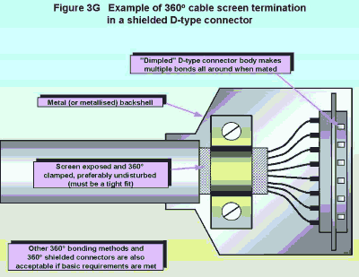
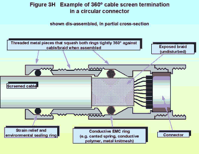
Many other types of connector and shield termination exist, but only those that make a 360° electrical bond between cable screen, the connector backshell, and the mating connector backshell (or the mounting panel of the mating connector) work well at RF. Any connector bonding technique that involves disturbing the lay of the foil or braid of the cable screen, or extending it with wires, will compromise the screening performance of the wire and/or the connector.
3.7.6 Bonding to the local RF reference
Where screened cables don't employ shielded connectors at their ends or at breaks, their exposed centre conductors can easily ruin their RF performance. Figures 3J shows how to use saddle-clamps to terminate cable screens to their local RF reference as close as possible to their terminals, so that the minimum length of signal conductors is exposed. The centre conductors should all be the same length and be as close together and as short as possible during their exposed length. DIN rail terminals are is shown in Figure 3J, but they could instead be screw or solder terminals or plastic-bodied connectors on an electronics unit. The best local RF reference for the screen of a cable to is the metal (or metallised) body of the electronics unit the cable plugs into, but if this is not possible the nearest local RF reference should be used instead.
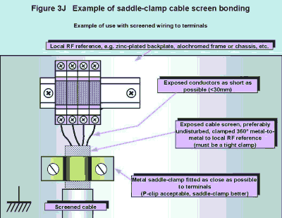
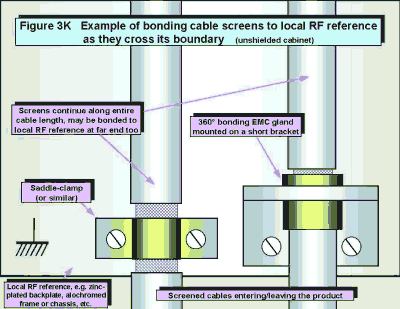
As well as bonding a cable's screen to its local RF reference at its ends or junctions, other screen bonds are needed. We will see later how a cable screen must bond 360° to the wall of a shielded enclosure if it is not to fatally compromise the RF shielding effectiveness of the enclosure. But where a shielded enclosure is not used it still makes sense to get the best RF performance from the existing structures, and this requires bonding all cable screens at the point where they first cross the boundary of the local RF reference, as shown by Figure 3K.
Despite their simplicity and ease of use, few EMC component manufacturers make saddle-clamps and designers often have to turn to the plumbing, pneumatics or hydraulics pages of their distributors' catalogues to find suitable parts. A number of alternatives to saddle-clamps are possible, and the inventive designer will have no trouble in creating new constructions to ease assembly of his cabinets. P-clips are often acceptable but their RF performance may not be as good as a saddleclamp because their single bond results in higher inductance.
A number of connector manufacturers now offer screen-terminating cable glands, which may be mounted on a short bracket from the local RF reference (see Figure 3K), or actually be mounted in (through) it. The types which bond with uniform pressure all around an undisturbed cable screen (e.g. an iris spring or knitmesh gasket) generally give the best RF performance.
Some manufacturers of enclosures and terminal systems sell their own cable screen bonding devices. As long as they provide 360° (full circle) bonding directly between the cable screen and the surface of the local RF reference they will give good performance. But beware - some of these attach the cables' screens to metal bars which have appreciable inductance, and these then usually connect to the local RF reference by a wire - adding even more inductance.
In situations where a screen bond needs to be made some tens of millimetres above the local RF reference, a wide metal bracket may be constructed that bonds to the RF reference at multiple points, with its upper surface castellated so that the cable screens may be terminated by saddle-clamps, P-clips, hose clips, stainless-steel cable ties, or other 360° methods. Although the metal bracket adds inductance and has a deleterious effect at higher frequencies, it is orders of magnitude better than pigtailing the screens.
All cable screen bonding methods should make a tight fit all around the periphery of their cable's screen (but without crushing the cable), and this tight fit must not become loose with age, wear and tear. It is always best not to disturb the lay of a cables' screen when 360° bonding it, but where lower shielding performance is acceptable a longer length of braid screen can be 'scrunched up' to make a tight fit in a slightly loose saddle-clamp or connector backshell screen clamp. Foil screened cables could wrap their drain wire around their undisturbed foil a few times under the clamp in similar circumstances.
3.7.7 Pigtails
This final bonding method uses a wired bond for screens of cables, often called 'pigtails', sketched in Figure 3L using the example of DIN-rail terminals. A similar arrangement may be used at the terminals of electronic units.

Pigtailed cable screens are very poor for EMC and so should be only used for insensitive or not-very-interfering signals. To get the best from a pigtail, keep the exposed centre conductors and the pigtail as short as possible (say, around 30 mm), and keep them all together by interleaving the pigtail bonding terminals with the signal terminals.
When using DIN rail terminals to connect pigtails to the local RF reference, the metal DIN rail itself should be bonded directly to the backplate (see Figure 3E) at both ends and at other positions along its length (preferably every 100mm or so).
3.8 Bonding cable screens at both ends
Cable screens should generally be bonded to their local RF references at both ends. This is because a screened cable which is only bonded at one end can only provide good shielding performance up to a frequency at which its length becomes a significant fraction of the wavelength. The higher the shielding required, the smaller the fraction of a wavelength. To put some rule-of-thumb numbers to this: for shielding of around 20dB the cable length should be less than one-twentieth of a wavelength. At 200MHz, a typical frequency for factory walkie-talkies, one wavelength in air is 1.5m and so one-twentieth of that is 75mm. This means that to maintain a shielding effectiveness of at least 20dB at up to 200MHz (to help prevent close proximity of 200MHz walkie-talkies resulting in interference), screened cables should have their screens bonded at both ends when their length exceeds 75mm.
Of course, nothing is as simple as this, and most types of screened cables will be losing their shielding effectiveness by 200MHz. Braided cables generally give better shielding performance than wrapped foil types, and are easier to terminate in 360° fittings. The better braid-screened cables generally have good optical braid coverage, and double-braid or braid-and-foil may be used to give better performance up to higher frequencies. Unlike all other types of screened cables, the shielding effectiveness of (expensive) 'superscreened' cables continues to improve as frequencies increase.
Screened cables can't provide any shielding at all from certain orientations of magnetic fields. Shielding from these requires a current to flow in the screen from one end to the other, which can't happen if the screen is only connected at one end.
Grounding both ends of the screens of external cables can cause high levels of current to flow in the screens, where there are significant potential differences between the 'earths' of the equipment at each end. This is a problem for the installation rather than the internal assembly of a product, and was dealt with in some detail in sections 2.5 through 2.7 of Part 2 of this series, which introduced the concept of the meshed common bonding network (MESH-CBN) and the parallel earthing conductor (PEC) both of which are themselves described in more detail in [1] and [2].
The need to bond cable screens at both ends does have a few implications for the assembly of a product:
- Create a local RF reference area (or volume) and keep all cables and electronics close to it (or inside it).
- Bond the screens of external cables to the local RF reference as soon as they cross its boundary (see 3.7.6 above and Figure 3K) even though they may also be bonded internally to the same reference.
- Provide fixings suitable for the connections of the external PECs (which could be wires, ducts, armour, trays, etc.)
Where an assembly provides for cable screen bonding at both ends, field replacement of one of the bonds by a capacitor is not too difficult, and removing the bond altogether is very easy. However, if the assembly was designed with screens bonded at only one end, then attempting to fit capacitors or 360° bonds at the other ends to solve problems in the field can be very difficult and time-consuming.
3.8.1 Never use cable screen as signal return
Wherever possible, never use the screen of a cable as a signal return. Always use a twisted pair or twisted triple or whatever number of conductors it takes to fully embrace all the send and return current paths for a given signal. Section 2.3 of Part 2 of this series goes into this issue in more detail.
3.9 Filters and their mounting
When choosing a filter, it is safest to assume that its attenuation at any frequency is no better than the worst-case derived from all of its matched 50W/50W, and its mismatched 100W/0.1W, and 0.1W/100W performance data for both common-mode and differential-mode (Asym. and Sym.). Merely using the 50W/50W attenuation curves can result in amplifying an unwanted noise frequency instead of attenuating it. Good filter manufacturers will provide all the above data as graphs, and Figure 3M shows how to use this to work out a filter's worst-case performance (the performance that can be relied upon).

The best filters have seamless metal bodies and must be bonded metal-to-metal to their local RF reference at all of their fixing points as shown in figures 3E and 3F. To help protect the electronics in a product from external EM disturbances, the filters fitted to external cables should be fitted at the point where the cable first crosses the boundary of the local RF reference. To help reduce emissions from noisy electronic units within a product which does not use a shielded enclosure, the filters should be fitted to the local RF reference as close as possible to the electronics concerned. Where filters are used to reduce the influence of external disturbances and to reduce emissions, their location in an unshielded enclosure can be a difficult compromise. See 3.10 below for the placement of filters in shielded enclosures, especially Figure 3R.
Filters fitted to the incoming mains supply should be placed so that the length of external mains cable which enters an enclosure is minimised, preferably less than 150mm for industrial cabinets. Smaller products should use a bulkhead mounted mains filter if at all possible, such as the popular IEC320 plug-inlet style, where no external mains wires penetrate the enclosure at all. Mains filters fitted prior to on/off switches (or door isolators in industrial cabinets) will stay live even when the power is switched off at the product, so touch protection and appropriate safety warnings for their terminals must be provided (check with the appropriate safety standards).
Filter input and output wires must never come anywhere near each other, as they are always one class of cable apart (see 3.12). Cascaded filters can interact and make the overall EMC performance worse than that of each filter on its own. For more on filtering used in products, refer to chapter 8 of [1], [12], and [13]. Part 4 of this series will deal with filters used at installation level.
3.10 Enclosure shielding
All of the above has assumed that a metal chassis, backplate, racking system, or enclosure was available and was used as a local RF reference, but did not assume that it was designed to provide any special shielding performance. Shielded enclosures may be needed because the electromagnetic threats in the intended operational environment are too severe for the electronic units used inside the enclosure, or because the environment needs to be protected from the disturbances emitted by the electronic units in the product.
Enclosure shielding requires metal enclosures (or plastic enclosures with metal coated surfaces or conductive fillers). Very careful attention to detail in design and assembly is needed if the shielding is to be successful. Apertures in a shield act as 'slot antennas', compromising shielding effectiveness (SE), as shown by Figure 3N for a single gap.
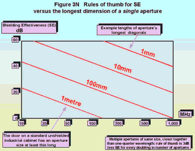
[3] describes good shielding practices for cabinets, and there is more information from an electronic designers point of view in reference [14]. Part 4 of this series will deal with shielding at installation level. Fully shielded cabinets complete with shielded windows and ventilation with excellent EMC performance may be purchased from a number of suppliers, and can easily be completely ruined by cutting apertures for door-mounted units, drilling holes, poor filter mounting, poor cable screening or screen bonding, or leaving doors open. Figure 3P shows how to use the clean box / dirty box method where a unit unavoidably has to penetrate the wall of a shielded enclosure. It is much better to position any displays behind shielded windows, especially where a good SE is needed or higher frequencies are to be controlled. Shielded touchscreens are possibly a good EMC solution to the problem of adding human-machine interfaces to shielded enclosures, as long as their shielded surface is electrically bonded all around the edge of their aperture in the enclosure.
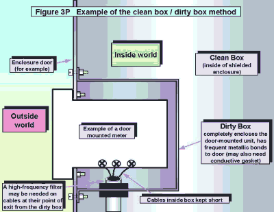
3.10.1 Screened cables entering a shielded enclosure
Every screened cable that enters a shielded enclosure must have its screen bonded to the enclosure's metal (or metallised) boundary at its point of entry using 360° screen-terminating glands or connectors, as shown by Figure 3Q. Saddle-clamps and pigtails must not be used for this job, except in very special circumstances where high frequencies (say, above 1MHz) are not a concern.

3.10.2 Unscreened cables entering a shielded enclosure
Every unscreened cable that enters a shielded enclosure must be fitted with a filter that provides a similar level of RF attenuation versus frequency as the SE required for the enclosure. This filter must be mounted at the point where the cable penetrates the metal (or metallised) boundary of the enclosure. Bulkhead mounting filters (such as filtered connectors) cause the least degradation of SE, as long as their metal bodies make a good electrical bond to the enclosure's metal surface all around their cut-out. Where modest levels of SE are required, it may be enough to rely on the bonds provided by the fixings of the filter, but for good SE - especially at higher frequencies - a conductive gasket is usually required to bond the filter's metal body to the enclosure's metal surface all around its periphery.
Where high-power conductors are to be filtered the best method is to use high-power feedthrough filters. A protective cover would be needed for their external terminals. An alternative is to use a 'screened room filter' - a boxed filter specifically designed for penetrating the walls of shielded enclosures without compromising their SE. These filters usually incorporate their own compartmented shields, and usually run their filtered outputs into the shielded enclosure through galvanised conduit.
Another alternative is to use the clean box / dirty box method with a lower cost screw-terminal type filter, as shown in Figure 3R. Attention to detail is needed to achieve high values of SE with this technique, especially minimising any gaps in the bonding around the edges of the 'dirty box', and reducing the coupling of high frequencies between the input and output cables inside the dirty box by keeping them both short and far away from each other. Even so, high-frequency bulkhead filters (or maybe just a few ferrite cylinders) may need to be fitted to one or both cables.

3.10.3 A segregated cabinet
Figure 3S shows a shielded cabinet which has been segregated into 'clean' and 'dirty' volumes, using the methods described above for terminating cables screens and screw-terminal filters. Instead of dividing a cabinet, some use an additional "dirty" cabinet bolted or (preferably) seam-welded to the side of the main "clean" cabinet.
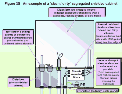
3.10.4 Doors, removable panels, displays, and ventilation
To achieve useful SEs, apertures in an enclosure must be few in number and small in size, so doors and removable panels must have frequent electrical bonds all around their edges. Bonding them with wires or straps is no good at all above a few MHz. Figure 3T shows the bonding of the doors and removable panels using a conductive EMC gasket (such as silicone rubber loaded with silver-plated glass beads). EMC gaskets are available that provide environmental as well as EMC sealing. Gaskets and their contact areas must not be painted, and careful choices of materials and metal finishes may be needed to prevent corrosion. [4] has a very good chapter on preventing galvanic corrosion.
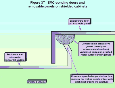
Spring fingers ('finger stock') may be used instead of gaskets around doors and removable panels, but may be more easily damaged in some applications. Many different styles of gaskets and spring fingers are available. Gasket choice requires balancing many physical considerations, such as compliance, compression set, and position in the galvanic series, with electrical ones such as contact resistance. An opening door may require a soft gasket (for ease of manual closing) which always springs back to its original shape, but these are often difficult to combine with low contact resistance.
Display screens are best viewed through shielded windows set into the doors of shielded cabinets. These windows may employ a thin metallic coating (often indium tin oxide, known as ITO) or a fine mesh of blackened wires. The meshes give better shielding performance, but can suffer from Moiré fringing effects if not selected carefully to suit the pixel size of the display. It is vital that all shielded windows make a direct electrical bond to the shielded enclosure's metal surface all around their circumference.
Ventilation apertures can be shielded by fitting a wire mesh (welded at each wire crossover in the mesh) over the aperture, with each wire electrically bonded metal-to-metal to the surface of the enclosure around the aperture's edge. Perforating the enclosure with a large number of small slots or holes can achieve the same shielding effect as fitting a wire grille over a large cut-out. A number of shielding manufacturers sell pre-assembled shielding grilles which may simply be bolted into place onto a plain metal surface because they have a conductive gasket all around their edge. Some of these are based on wire mesh, and some on more exotic technologies such as wire wool or honeycomb metal to give better SEs.
Some manufacturers of shielded cabinets may use other techniques (such as waveguides-below-cutoff) which don't rely on grilles or meshes. If you see a ventilation aperture without any visible shielding over it, ask the manufacturer what he has done to prevent this from compromising the enclosure's SE.
3.10.5 Interconnecting shielded enclosures
Refer to section 2.9 and Figure 2T of Part 2 of this series.
3.11 Connector panels
There should ideally be only a single connector panel for each enclosure, so that all external cables enter the internal electronics' local RF reference area or volume at one of its sides or edges. This is so that (in conjunction with the other techniques described here) the common-mode currents which can flow in long external cables, especially in some industrial environments or during thunderstorms, will flow from cable to cable via the connector panel or backplate edge through the screen-terminations and filters mounted in that area. As a result these circulating currents will tend not to flow through the rest of the enclosure or RF reference, or through the internal electronics and their cables, and this helps to prevent interference. For more on this, refer to section 2.8.3 of Part 2 of this series, especially Figure 2S.
3.12 Cable classes and segregation
Cables internal to a product should be split into at least 4 classes as described in section 2.8.1 of Part 2 of this series (which will not be repeated here). These classes must be physically segregated within the product at all times, and long parallel runs should not be any closer than 150mm, if possible. Cables should always run as close as possible to their local RF reference, and if cable classes must cross over each other they should only do so at right angles. Where 150mm segregation is not practical screened cables may need to have a higher shielding specification and/or higher-quality screen terminations at their ends (e.g. shielded connectors or glands instead of saddleclamps or pigtails), and unscreened cables may need to be replaced with screened types.
3.12.1 Cables from devices that use computing techniques
Many electronic devices have I/O signals that would appear to be relatively benign in EMC terms (e.g. audio outputs, inputs from pushbuttons, thermocouple inputs, indicator lamp outputs). What is often not realised is that where there is digital processing within a unit, these I/Os can carry high levels of common-mode noise which is unrelated to the I/O signals themselves, and which can have a very much higher frequency content.
Harmonics of internal clock and data busses are usually the chief culprits, often giving common-mode emissions in the hundreds of MHz. So, unless the manufacturer of the electronic device that employs digital processing internally clearly states otherwise, always expect to have to use screened cables (and no pigtails) or filters for such signals.
3.12.2 External cable classification when RF transmitters are nearby
Section 2.8.1 classifies cables according to the signals they carry, but it is also necessary to consider the effect of the external environment on the cables. If there are powerful radio, TV, or radar transmitters nearby this can create an especially hostile environment for external cables. Examples include broadcasting stations, hand-held walkie-talkies, vehicle mobiles (such as in the garages of emergency services vehicles). The acceptable proximity of these transmitters depends on their RF power, and formulae and tables are available to help determine whether such transmitters are a threat, such as [15].
Walkie-talkies used by electricians, installers, builders, operators, security guards, and maintenance personnel can be a particular nuisance as they could be very close to cables, and it may be necessary to limit the areas where they may be used. Some RF production equipment (such as induction furnaces, dielectric heaters, plastic welders or sealers, microwave dryers, etc.) also emit very high levels of radio frequency energy and can cause great problems for cables passing close to them.
Where such problems are known or suspected (the customer should be able to furnish details) signal or power cables entering or leaving the panel should always be treated as either class 1 or 4 and use screening and / or filtering as appropriate. However, if the external cables are always confined to sealed RF-bonded conduits (i.e. rectangular conduit with RF-bonded covers, or circular conduit) in the area of their RF exposure, then they may be able to use the cable types normal for their class.
3.13 The layout inside a product
Carefully position the various electronic, electrical, pneumatic, hydraulic, etc., units inside the product to keep sensitive units such as millivolt input transducer amplifiers or programmable logic controllers (PLCs) well away from electrically noisy units such as relays and contactors or switch-mode power converters, and also to help achieve segregation of the different cable classes. Figure 3U is a sketch of an example backplate layout for a simple industrial control panel.
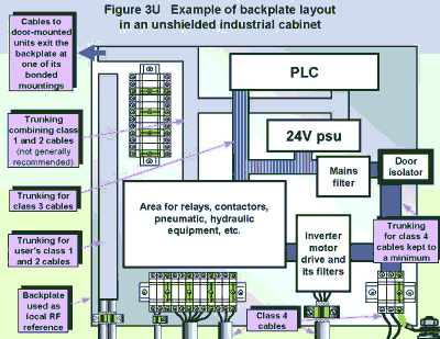
Notice that the class 1 and 2 cables in Figure 3U were run in the same trunking - this was a compromise that was felt to be acceptable because the panel was very small, and because there were very few class 1 signals and they were not very sensitive. There is nothing wrong with compromise, it is the life-blood of engineering after all, but it is very important that compromises are determined case-by-case by people competent in the disciplines involved (EMC in this case).
As in Figure 3U, try to have no internal CLASS 4 cables at all, or at least minimise their internal lengths as much as possible. This means fitting units such as switch-mode power supplies and inverter motor drives near to the edge of the product, and / or filtering any class 4 incoming mains supplies at their point of entry to make them into class 3 or 2.
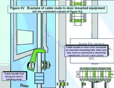
Figure 3V shows the best cable route to door-mounted units in an unshielded industrial cabinet. The cables are run close to a local RF reference over their whole length, which means exiting the backplate at one of its electrically bonded mounting points, and crossing the door hinge strapped to the short braid which bonds the door to its nearby cabinet wall. Hinges cannot be relied upon to electrically bond doors to enclosures, as they usually contain grease or plastic inserts. In a well-shielded cabinet the door will be bonded all around by a conductive gasket, so it does not matter where the cables cross the hinge area.
3.14 References and further reading
 © Nutwood UK Ltd 2001 |
Eddystone Court - De Lank Lane St Breward - BODMIN - PL30 4NQ Tel: +44 (0)1208 851530 - Fax: +44 (0)1208 850871 nutwooduk@nutwood.eu.com |
|
|
|