Heat Shrink Solutions to EMC
Solving EMI/RFI Problems with Conductive, Shielded Heat Shrink Tubing
By Emil E. Millas, Methode Development Company
Introduction
Virtually all of today’s advanced electronic systems, especially high speed computer and data communications equipment, are susceptible to electromagnetic interference (EMI) and radio frequency interference (RFI). This susceptibility can manifest itself as a sensitivity to incoming EMI/RFI which causes the system to malfunction or the EMI/RFI problem can be that the equipment generates too much outgoing EMI/RFI, causing problems in other equipment nearby.
EMI/RFI considerations are important and so the US FCE and Europe’s CE have their strict guidelines on acceptable EMI/RFI performance in electronic systems. And manufacturers must conform.
The Problem
On the surface, designing for correct EMI/RFI performance appears to be just another task in the procedures of design but below the surface, the real world conspires to make things more complicated. That’s because the EMI/RFI performance of an engineering prototype may be completely different to that of an actual production unit. This means that discovering a new piece of equipment does not meet FCC or CE EMI/RFI guidelines may not be until after pilot production units have been built and tested. At this point, if there is a problem, the solution is often left to a packaging designer who may not have the necessary high degree of knowledge and experience of EMI/RFI and its problems.
EMI/RFI problems frequently – but not always - occur at the junction between a shielded cable and its connector. A common solution is to use a metal or metallised plastic connector, and to solder the shield of the cable to this connector. Alternatively, the area of the junction might be wrapped with copper tape and then soldered.
While these types of solution can work, they are expensive, labour intensive and due to the fact that they are manually constructed, are often inconsistent in performance. For example, if the wrapped copper tape fails to cover even a very small area, the cable assembly may still emit unacceptably high levels of EMI/RFI. Moreover, if the EMI/RFI problems are not pinpointed to the cable and connector junction, then solving them is likely to be even more difficult.
The Solution
One product developed to solve many of these problems is a heat shrink tubing featuring a metallic conductive ink coated on the inside. Methode Development Company’s shrinkMate can solve a number of EMI/RFI problems easily and inexpensively, without requiring the designer, engineer or indeed user to have in-depth knowledge of electromagnetic radiation and the respective shielding issues.
In use, appropriate size of tubing is simply placed over the components or assemblies to be shielded and heat is applied. When the tubing shrinks, the inner metallic surface is placed in close contact with everything beneath it, resulting in a 100% covering shield that is also electrically conductive. Furthermore, this product can also be used to shield cable assemblies with plastic connectors.

Effective applications
The many applications of shrinkMate serve reference to it effectiveness. One such use has been in a high tech fire fighter’s helmet where the manufacturer had a new design incorporating advanced systems such as night vision, heat sensing and two way communications. However, when the helmet went into production, it emerged that the various electronic systems, all of which were in close proximity to one another, were in fact interfering with each other. Cross talk was so bad that it was virtually impossible to use more than one of the systems at the same time. At this point, the product was unusable.
Using shrinkMate tubing to cover the various cables running inside the helmet easily solved the EMI/RFI problems. Furthermore, the simple solution avoided the need to design or fabricate shields or metal enclosures thus reducing the complexity and the weight of the helmet. The tubing was also able to withstand rapid thermal gradients, such as those experienced by fire fighters leaving the heat inside a burning building and going outside to severe winter weather.
Another manufacturer who had designed a cable assembly using an RJ45 telephone jack, needed to include a circular grommet to act as a strain relief. The problem was however, that this entire assembly, with a rectangular jack and a round grommet, had to be shielded. And shielding irregularly shaped combinations of components can be extremely difficult. With shrinkMate, the manufacturer simply slid the entire assembly inside a piece of shrinkMate tubing, and once shrunk to size, the tubing solved the problem.
For an agricultural equipment sensor system, a third manufacturer had designed and tooled the housing. However, when the sensor and its associated circuit board were assembled inside, subsequent testing showed unacceptable EMI/RFI performance. A major problem facing the manufacturer at this stage was that there already had been a significant investment in tooling and designing a new housing would have been prohibitive.
The simple solution was to place the sensor and the circuit board inside a special piece of shrinkMate. The tubing had to have a wall so thin that the entire assembly still fitted inside the existing housing, solving the EMI/RFI problem without losing the substantial investment in the tooling for the original housing.
While these applications show how shielded, conductive heat shrink tubing have solved EMI/RFI problems, it is clear that not all EMI/RFI issues can be fixed with a single product like shrinkMate. In cases where EMI/RFI leakage occurs, for example, around the door of a large shielded enclosure, it may be necessary to use a flexible metal gasket. Other systems may require different types of solutions. But for sub-systems and components which can fit inside the tubing, shrinkMate is a highly effective and easy to install solution.
Compliance kit
Methode Electronics Europe now has available, an EMC compliance kit containing a wide selection of EMC shrinkMate heat shrink tubing. The kit enables test connector and cable assemblies to be quickly and easily constructed with high levels of EMI/RFI and ESD shielding.
Notably, EMC shrinkMate meets stringent aerospace industry specifications for outgassing. Included ARE ASTM E-595, NASA SPR-0022A and ESA PSS-010702 covering vacuum stability requirements of polymeric materials in spacecraft appliations of mass loss and collected volatile condensable materials.
EMC shrinkMate, rated at Mil Std R-46846, is heat shrinkable polyolefin tubing coated on the inside with Methode’s unique polymer thick film silver ink to provide a complete shield around a connector and cable assembly. The resultant assembly eliminates significantly the source of EMC leakage and, compared to ferrite beads, the EMC shrinkMate solution effectively reduces the ingress and egress of EMI and RFI, as well as penetration into the assembly by external contaminants such as dust, moisture and oil.
EMC compliant ‘joints’ using EMC shrinkMate require no soldering, thus enabling fast and easy manufacturing of co-axial cable butt joints and cable to connector housing joints. The polyolefin tubing also eliminates most of the problems associated with providing an EMI/RFI/ESD shield between solderable and non-solderable surfaces such as stamped metals, plated finishes and shielding paints.
The new Methode kit comprises a selection of 6in lengths of 1/4in, 3/8in, 1/2in, 3/4in and 1in ID EMC shrinkMate tubing. As well as for testing applications, the EMC compliance kit is ideal in prototyping and pilot production environments, enabling production quantities to be subsequently ordered as required. EMC shrinkMate also provides major savings by eliminating soldering in connector assemblies and is ideal for subsequent over-moulding.
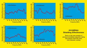
EMC shrinkMate is available in production quantities from 1/8 to 5in ID. Custom formulations, such as the special thin walled version for the agricultural sensor, are also available. shrinkMate provides a low resistance shield of less than 1W/in. Shielding effectiveness varies according to tube diameter and frequency, ranging from 40dB ~ 82dB over 30MHz ~ 1GHz. Operating temperature range is –55 ~ +135oC.
Methode Electronics, Inc., with 4000 employees in 21 plants worldwide, manufactures component devices for OEMs for use in information processing and networking equipment, voice and data communications systems, consumer electronics, automotive, aerospace and industrial applications. Methode products employ electrical, electronics and optical technologies as sensors, interconnections and controls. Of around 18,000 holders of publicly traded stock, approximately 12% is owned by Methode employees.
Emil E. Millas is Sales & Marketing Manager at Methode Development Company, a division of Methode Electronics Inc.
For further information, please contact Tom Shaw, Managing Director at Methode Electronics Europe Ltd, Vale of Leven Industrial Estate, Dumbarton, Dunbartonshire G82 3PD, Scotland.
Telephone: +44 (0)1389-732 123. Fax: +44 (0)1389-732 777.
E-mail: tom.shaw@meel.com Web site: www.methode.com.