EMC Concepts
By Mark Shaw, Rittal Limited
Interference fields arising in the environment can disturb a device and the operation of the device can at the same time itself produce interference that affects the environment. This applies both to industrial applications and to applications used in the home.
The basic demands made on devices with regard to electromagnetic compatibility (EMC) are thus:
· Attainment of a defined interference immunity (protection against external interference fields)
· Prevention or reduction of emitted interference (protection for the environment against own interference fields)
Possible sources or subjects of electromagnetic disturbance are:
· Mains connection cables
· Signal and control cables
· Electrical of electronic modules which emit electromagnetic fields or which can themselves be disturbed by such fields
However a typical metal housing already offers electrical devices significant protection against electromagnetic interference fields. In practical applications, it has been proven that in more than 95 % of all applications standard enclosures or housing offer sufficient shielding to guarantee electromagnetic compatibility.
Shielding against especially intensive electromagnetic interference.
Especially intensive interference fields are produced, for example, in microwave drying, by electrical discharge machining systems and by high-frequency welding equipment. In such cases standard enclosures and housings are often no longer adequate and it is recommended instead to employ a special EMC enclosure.
High shielding effect – how it’s done.
A practically unbroken electro conductive connection is achieved between the outer surfaces of the housing by fitting a special conductive seal. The inner surfaces and seal edges remain unpainted. The aluminium-zinc coating of the base material provides corrosion protection. The quality of the housing in practical use can only be as high as the quality of its original manufacturing. The integrity of the shielding must also be taken into account where cutouts are made for inspection windows or climate control components.
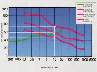
In the above shield attenuation diagram, the weakening of the fields by the housing is plotted against the frequency on a logarithmic scale.
· 20 dB shield attenuation corresponds to a weakening by a factor 10
· 40 dB shield attenuation corresponds to a weakening by a factor 100
· 60 dB shield attenuation corresponds to a weakening by a factor 1000
· and so on
The diagrams are based on shield attenuation measurements performed in accordance with relevant testing regulations (MIL-STD 285, VG 95 373 Part 15)
To assist with EMC some basic design guidelines should be followed which will help to lessen the attenuation required;
· Ideally there should be low and high frequency potential equalisation between all metallic masses, enclosure, machine and system components, which should be meshed as closely as possible.
· Avoid large cable loops; lay current-carrying cables as close as possible to the reference potential.
· Maximum possible cross section, large area conductive mounting, low inductive (a rectangle is better than a round conductor)
· The mounting plate as a potential equalisation surface: all components with a conductive housing can be conductively mounted with a large contact area.
· Cable glands can be contacted directly at the point of cable entry, where possible.
· Use right-angled cable crossover wherever possible and ensure adequate distance between interference-emitting and sensitive cables.
This contribution to the EMC topic is intended to give an insight into the practical application of screening for enclosures. It has become quite clear that the screening technology must take a multitude of individual problems into consideration and that the design of an enclosure to form as homogenous a screened enclosure as possible requires a great deal of care and eye for detail.
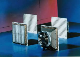
Accessories should also be EMC compliant such as the EMC filter fans from Rittal
Mark Shaw, 45, joined Rittal over 20 years ago in the sales department and during his time has seen many changes in the enclosures market. From a comprehensive product range Rittal can provide complete enclosure solutions from stock and Mark, who is based at Rittal’s UK headquarters in Hellaby, South Yorkshire, has developed with the company to his current position as Product Manager where he specialises in the fields of Industrial Enclosures, Eex, EMC applications and Busbar Systems. Shielding against typical electromagnetic interferences.
For a copy of Rittal’s comprehensive EMC range brochure, Enter Enquiry No. 36