|
EMI Noise Reduction Tape using Magnetic Alloy Films
By Ian Kwan, Product Manager, Coteau Vert USA, Inc.
Background The recent progress of information technology has led to the development of high-speed information technology equipment, which contains many digital processing circuits. These circuits are the source of disturbances and some disturbances are emitted from interface cables. Therefore, it is important to reduce the emission level from the interface cable to satisfy emission requirements.
The Current Situation Although ferrite cores are widely used as countermeasure devices against emission from interface cables, their diameters are usually several times that of the cable and the mass are several ten grams. Consequently, cables with a ferrite core can only be employed in limited applications. In particular, these cables are not suitable for use in equipment that has to be light and compact, or in an environment in which space is a constraint. Further more, effectiveness of a ferrite core in reducing noise depends on its position in the cable and the likelihood of it causing resonance. This is because a ferrite core creates a lumped impedance at a specific position in the cable and allows a noise current to flow to the core.
A New Approach To address the shortfalls of using ferrite core in cable, a magnetic tape incorporating layers of magnetic alloy film has been developed by NTT-Advanced Technology Corp. (subsidiary of Nippon Telegraph and Telephone Corp.) to reduce the EMI current in an electrical cable. The magnetic tape, named NoiseBEAT tapeTM, possesses high electromagnetic wave absorption properties. It has a thickness of 60 µm and weighs less than 4 g/m (non-aluminum type). Due to its thin and lightweight characteristics, NoiseBEAT tape can be wrapped inside the cable. We would explain the superiority of the magnetic film over ferrite core below. The noise emission reduction, noise-reduction efficiency, and durability of NoiseBEAT tape would also be discussed.
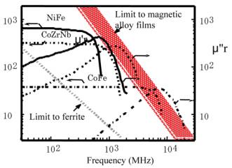
High-Loss Mechanisms This section explains the advantages of the magnetic film compared to a ferrite core. The impedance of a magnetic material, Z (= jX + R), is proportional to the permeability, and can be written as: çZçµçwV (jm'r + m"r )ç, (1) where is angular frequency, V is the volume of the magnetic material, and µ'r & µ"r are the relative permeability. X is the reactance. R is the loss component and Eq. (1) shows that a high µ"r material must be used to obtain high loss with a smaller volume. Ferrite does not have high µ"r in high-frequency range of several hundred megahertz because the product of the permeability and the frequency bandwidth is restricted by Snoek’s limit1. However, soft magnetic-alloy films can exceed this limit as show in Fig. 1, and a product two orders of magnitude larger than the product for ferrite has been obtained2. Thus, a soft magnetic-alloy film with high concentrates the magnetic flux and produces high loss. This is one reason why soft magnetic-alloy films need only a small volume to reduce EMI noise.
Fig.1 Dependence of the complex permeability of the magnetic materials on frequency
The relative permeability of a magnetic-alloy film is given by the following equation3. µ'r = (µ'r,0 /q){sinhq + sinq)/(coshq + cosq)}, (2) µ"r = (µ'r,0 /q){sinhq - sinq)/(coshq + cosq)}, (3) Where q is the film thickness normalized by the skin depth, d, (q = t/ d) and µ'r,0 is the relative permeability at w ® 0
For a fixed frequency, Eq.(1) is rewritten as X µ qµ'r and R µ qµ"r. It is shown that R is almost constant and comparable to X when è is three or more. Thus the optimum thickness of the magnetic film to generate a high loss with minimal volume is only about three times the skin depth. This optimum condition applies to the lowest frequency in the relevant range, and is also sufficient at higher frequencies where it will lead to the same amount of loss. The optimum thickness was only a few micrometers at 30MHz because of the low resistively of the magnetic alloy film. Hence, this is a second reason for the high noise reduction efficiency of the magnetic alloy film.
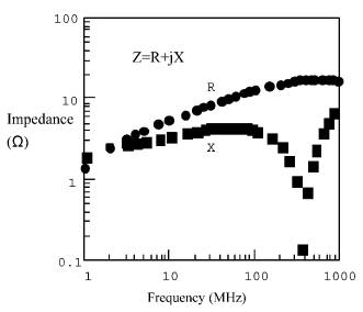
Fig.2 Measured impedance of the magnetic film.
Figure 2 shows the impedance of the magnetic film measured by the impedance analyzer. This impedance (R: resistance, X: reactance) was obtained by subtracting the impedance of the wire alone from that of the inductor. The resistance R corresponding to the magnetic loss equaled to X at 2MHz, but was much larger than X above 30MHz. The rapid fall in X at about 400MHz was caused by the ferromagnetic resonance as show in Fig.1 (higher-µr material yields lower resonance frequency).
Tape Structure The magnetic film was laminated with resin films using an adhesive to provide the necessary strength as well as to insulate films from each other and from the cable shielding while maintaining the desired film thickness. By selecting an appropriate resin material (PET) and forming small margins on both sides of the magnetic film to protect the edges, a tape with resin films that are as thin as the magnetic film is strong, light, and flexible.
Fig.3 Structure of the fabricated magnetic tape
The structure of the fabricated magnetic tape (NoiseBEAT Tape) is shown in Fig. 3 and the specifications are listed in Table 1. NoiseBEAT Tape has four types: with and without aluminum foil (types A & B) with a width of 13.5 or 21mm. The tape with the aluminum foil (type B) was fabricated to improve the cable pliability by replacing the outer shielding used in conventional multi-shielded cable. This tape has a further advantage: to process to wind the outer shielding onto the cable is unnecessary. The tape width was selected based on the cable diameter which ranged from 4 to 10mm.
Table 1. NoiseBEAT Tape Specifications
Noise Emission Reduction
Fig. 4 Measurement setup
The radiated field strength from the fabricated cables was measured in the range from 30 to 300MHz by the ten-meter-method in a semi-anechoic chamber (Fig. 4). The measurements were done using an equipment model in which a 7-m-lng cable was connected between the shielded cabinet, and digital signals driven by FAST-TTL devices were transmitted through the cable. The cable was connected to the rear of the subrack with connectors. This setup ensures the dominance of the emission from the cable because the emission from the printed circuit boards is suppressed by the shielded cabinets. The clock frequency was set to about 8MHz to obtain a spectrum distributed in the measurement frequency range. The noise reduction was measured by substituting the conventional STP cable with one having the magnetic tape.
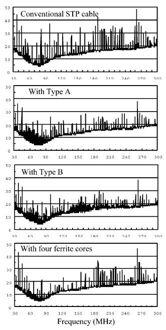
Fig. 5 shows the measured electrical-field spectrum. The spectrum measured using an STP cable loaded with two ferrite cores at each end is also shown. The outer and inner diameters were 15mm and 9mm, respectively, and the length of the ferrite core was 27mm. The strength of the spectrum was decreased over the entire range by up to about 10dB when the magnetic tape was used.
Fig. 5 Measured radiated field spectrum
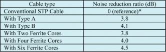
Table 2 summarizes the measurement results. The noise reduction ratio indicates the difference between the average of the twenty highest peaks measured with the cable having the magnetic tape or the ferrite cores and that measured with the conventional STP cable. This ration with the magnetic tape was 3.8 to 4.1dB, which was close to the ratio with the four ferrite cores (4.0dB).
*32.2 dBµV/m (average of 20 highest peaks) Table 2 – Measured noise emission reduction ratio
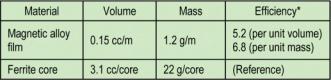
Noise Reduction Efficiency The noise reduction ratio per unit volume or mass of the magnetic material can be used to evaluate noise reduction efficiency because the materials’ high frequency loss is proportional to the volume. Table 3 compares the noise reduction efficiency of the magnetic film with that of the ferrite core. The estimated efficiency of the magnetic film was about six times that of the ferrite core, assuming that noise reduction ratio induced by the magnetic tape wound around the 7-m-long cable was equal to that induced by the four ferrite cores based on the noise-emission measurements.
* Ratio of 4 ferrite cores to magnetic alloy film in 7m-long cable Table 3 Noise reduction efficiency
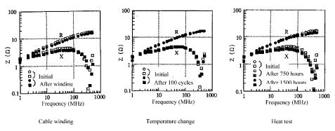
Durability The impedance changes caused by mechanical stress associated with the winding process and environmental temperature change were measured to evaluate the durability of the magnetic tape. The magnetic tape extracted form the cable and that from a roll taken from the same production lot were compared through a mechanical stress test. The temperature test was carried out during 100 cycles in which the temperature was alternately fixed at -25°C and 85°C, each for one hour. The temperature was fixed at 85°C for up to 1500 hours for the heat test.
The measurement results are shown in above figure. The decrease in R associated with each test was 10% or less, demonstrating that the magnetic tape has sufficient durability for practical use.
Conclusion The magnetic noise-reduction tape, NoiseBEAT Tape, achieves high-loss characteristics above 30MHz. The strength required to allow winding of the magnetic film onto a cable was obtained by laminating the magnetic film with resin films leaving a small margin in each side. This magnetic film is thin and flexible enough that it can be added within the cable sheath, and thus uniformly distribution the impedance over the entire cable length. Replacing the cable shielding with a magnetic tape containing an aluminum foil improves the cable pliability.
When using the NoiseBEAT Tape, we obtained noise reduction ratios of 4 to 5dB for both radiated emission and surge immunity. No significant degradation was observed in the mechanical and environmental tests, showing that these tapes are durable enough for practical use. In conclusion, all these competitive advantages make NoiseBEAT Tape a better choice than ferrite core in noise-reduction for cables. In addition, NoiseBEAT Tape is applicable to various EMI-reduction components used in compact and lightweight equipment due to its thin and light characteristics.
1 J. Snoek, “Dispersion and absorption in magnetic ferrite at frequencies above one Mc/s, “ Physica, vol. 14, no.4, pp 207-217, 1948 2 M. Senda and O. Ishii, “Permeability measurement in GHz range for soft magnetic films using the M/C/M inductance-line,” IEEE Trans. Magn., vol. 31, no. 2, pp. 960-965, 1995 3 R. Bozorth, “Ferromagnetism, “ D. Van Nostrand Co., Princeton, N.J., p. 769, 1951
Article based on “EMI Noise Reduction Tape Containing Magnetic-Alloy Film,”- T. Mori and M. Senda, IEICE Trans. Commun., VOL. E83-B, No. 3, pp. 600-607, 2000
Ian Kwan can be contacted on tel: +1 805-497-2123, email: ikwan@coteauvert-us.com or visit the website http://www.coteauvert-us.com/ NoiseBEAT Tape is developed and manufactured by NTT Advanced Technology Corporation.
For further information contact Lee Matthews at SystemWare Europe Tel: +44 (0)11767 640855 or email: lee@sysware.com
|