|
Electromagnetic Interference (EMI) Inside a Hard Disk Drive Due to External ESD
By Douglas C. Smith, D.C. Smith Consultants and Al Wallash, Maxtor Corporation
GMR recording heads used in today’s hard disk drives are very sensitive to damage from impulsive current transients caused by electrostatic discharge (ESD) and even the electromagnetic interference (EMI) due to a nearby ESD event.[1,2,3] In this work, we measure the EMI inside a hard disk drive due to a variety of ESD events outside the drive enclosure.
Introduction Previous papers have shown that it is possible to damage GMR heads just from the electromagnetic radiation from an ESD event at distances greater than a meter.[1] A question that has not been explored is how much shielding, and therefore protection, does the disk drive assembly afford to the GMR heads inside. Data was taken to measure the amount of EMI inside the drive assembly in response to ESD outside of the drive.
Test Setup A disk drive was prepared for measuring the EMI inside the drive and ESD was applied both directly and indirectly to the drive.
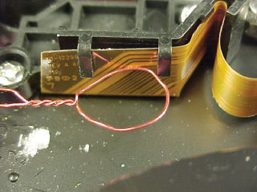
Drive Preparation Figures 1 and 2 show how the drive was modified to measure EMI inside the drive. Two SMA connectors were mounted in the side of the drive enclosure and a small loop was placed inside the drive. The position of the loop near the flex cable to the head assembly is shown in Figure 3. Positioning the loop next to the flex cable allowed it to measure an Mdi/dt voltage drop estimate of the drop along the cable as well as internal fields.
The second SMA connector was used to make sure that the scope and connecting cable was not allowing ESD generated EMI to contaminate the measurement.
Figure 1: SMA Connectors Mounted on Drive Case
Figure 2A: View of Loop Inside of Drive
Figure 2B: View of Loop Positioning Near Flex Cable
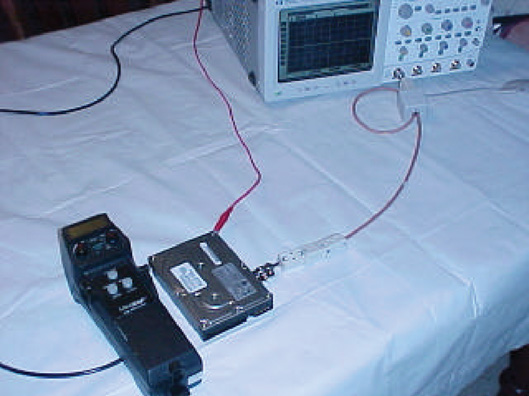
ESD Test Configuration Figure 3 shows the general test setup. The drive was grounded to the scope chassis. This wire served to carry most of the ESD current to the back of the scope chassis. ESD currents flowing on the coaxial cable connected to the scope input were minimized by the presence of the grounding wire and the ferrite cores on both ends of the coaxial cable.
Figure 3: General ESD Test Setup
ESD stress was applied to the drive in three ways:
· To pins of the power and IDE connectors · To the drive enclosure · By radiation from a nearby ESD event
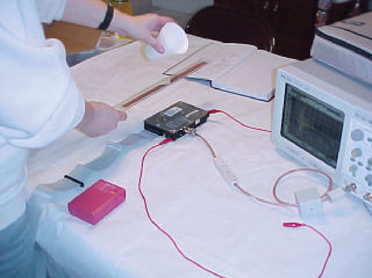
Application of ESD to the drive is shown in Figures 4, 5, and 6. Figure 4 shows the setup for application of ESD to the connector pins. Figure 5 shows direct application of ESD to the drive enclosure and Figure 6 shows radiated EMI from an ESD event. The EMI generator is made from two pieces of copper foil tape.[4]
Figure 4: Applying ESD to Connector Pins
Figure 5: Applying ESD to Drive Enclosure
Figure 6: Indirect EMI Applied to Drive
EMI is generated in Figure 6 by using a static charge to induce sparks between two pieces of copper foil separated by less than 1 mm. “Pops” in the nearby AM radio confirm that sparks are taking place. The resulting EMI is very intense. A one meter flat IDE cable and a one meter lead connected pin #1 of the power connector were added to simulate connections to the drive.
The ESD simulator was a KeyTek MiniZap used without the IEC tip. This produces faster rising edges more representative of real ESD.
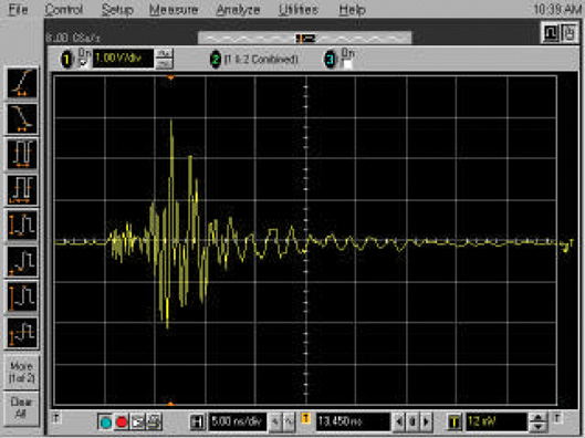
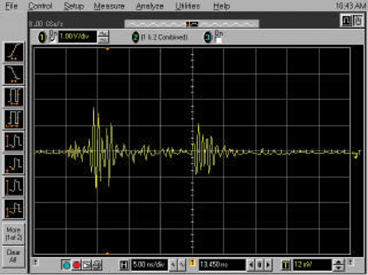
Results Discharges to Power/Gnd Pins ESD applied to the connector pins yielded surprising results. Figure 7 shows the result of a 3 kV contact discharge to the corner pin of the power connector, pin 1. Almost 3 Volts peak was delivered by the loop installed in the drive to the 50W load at the scope! This represents 60 mA, enough to damage a head if the current were flowing in a GMR head. When the coaxial cable, high quality RG-142B/U, was moved to the “null” SMA connector, the scope registered only a 150 mV peak signal.
Figure 7: Loop Output from Discharge to Power Pin #1
This result raises the possibility that insertion of a power cable into a drive that has a charge on it, could potentially damage the GMR head.
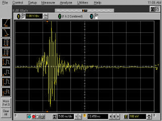
Figure 8 shows the loop pickup when the contact discharge was applied to one of the jumper pins. This is another point where ESD is likely to happen as a tool is used to insert or remove the jumper.
The peak value of about 1.5 Volts resulted in about 30 mA into the 50W load, a level that is potentially dangerous to a GMR head. Also notable is the double burst of signal. Possibly a secondary spark in the drive caused this, but that has not been confirmed.
The null experiment (connecting the coax cable to the shorted SMA jack) yielded an output of 150 mV peak, within acceptable limits. This would have been lower if the jack were shorted with foil rather than a wire which formed a small loop with its resultant pickup.
Figure 8: Loop Output from Discharge to Power Pin #1
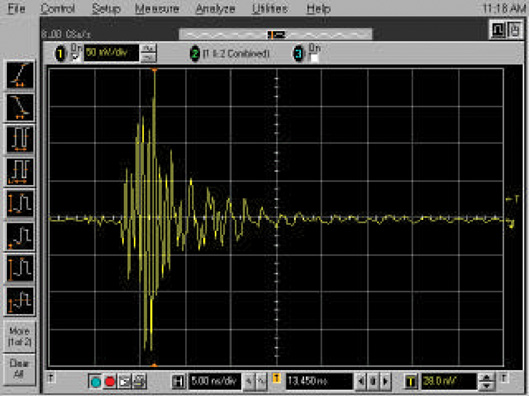
Discharges to Disk Enclosure Figure 9 shows the loop pickup from a direct 3 kV contact discharge to the top of the disk enclosure at the screw on the mid-point of the side, near the SMA connectors. The result is similar to other locations on the top of the drive at about 1 Volt peak.
Figure 9: Loop Output from Discharge to Top of Drive Enclosure
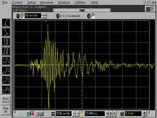
The amplitude of the signal in the pickup loop was slightly smaller than when the ESD was applied to the two pins in the connector shown in Figures 7 and 8. The null experiment result was 150 mV. Figure 10 shows the result of the contact discharge at the edge of the top of the drive directly over the SMA connectors. The output is about 3.5 Volts peak with a null experiment value of 1 Volt peak. The small loop formed on the null experiment connector contributed to the result of the null experiment as did other stray pickup. Note that the proximity of the discharge to the SMA connectors coupled with the fact that the drive gasket was non-conducting, allowed ESD currents into the drive between the cover and base.
Figure 10: Loop Output from Discharge to Edge Near the SMA Connectors.
Copper tape was placed along the edge of the drive on the same side as the SMA connectors to simulate the effect of a conductive gasket. The main loop output fell significantly from 3.5 Volts peak to about 1 Volt peak for the same discharge that resulted in Figure 10. This result suggests that a conductive gasket between the drive cover and body could provide significant shielding of the drive internal components from external ESD.
Radiated EMI from ESD Events Radiated tests were made with the test setup as shown in Figure 6 and with a KeyTek MiniZap ESD simulator. Contact discharges at 4 kV were done to the simulator ground lead about 1 meter from the drive assembly.
Figure 11 shows the sensing loop output when the copper foil gap spark generator was held as in Figure 6. Such an arrangement produces fairly severe radiated EMI at such close range and has induced a wide range of equipment problems in other settings. The peak voltage recorded was about 200 mV with the null experiment SMA output registering about 10 mV.
Figure 12 shows the result when the ESD simulator was contact discharged to its ground lead at a distance of about 1 meter. This is the arrangement than was able to melt a GMR head in open air from this distance in a previous paper.[1] The result was about 200 mV peak as with the copper foil spark gap. The null experiment was about 30 mV for this experiment.
Figure 11: Loop Pickup from Copper Tape Spark Gap
Figure 12: Loop Pickup from ESD Simulator Self-Discharge
A level of 200 mV represents about 5 mA into 50W. This is not as severe a problem as the direct discharges. As heads get more sensitive problems could arise though.
An observation on the above waveforms: Some of the waveforms above (Figures 7,8,9, 10, and 12) have a small amount of EMI arriving at the scope before the main event by about 4 ns. Figure 11 does not show this and was the only waveform not using the ESD simulator. The amount of initial noise was also about the level of the null experiments. Note the time delay of the main event corresponds to the difference in propagation time between the simulator and scope in free space (~2 ns) versus the delay through the coax (~6 ns). This suggests that direct radiation from the intense contact discharge might be radiating a small signal into the oscilloscope. One must be very careful when using test equipment in the vicinity of ESD.
Conclusions Initial tests have shown that there is a possibility that external ESD can produce significant induced voltages inside of a disk drive. The main problem is with direct discharges, however radiated events may become a problem in the future unless the shielding effectiveness of the enclosure is improved.
The data suggests that the use of a conductive gasket on the drive cover will substantially reduce the fields and induced voltages in the drive. Further work is needed to measure the actual voltage across the GMR heads under ESD conditions.
Acknowledgements We wish to express our appreciation to Agilent Technologies and KeyTek Instruments. These companies provided the test equipment (Infinium Oscilloscope and MiniZap ESD simulator) used in this paper.
References [1]Al Wallash and Doug Smith, “Damage to Magnetic Recording Heads Due to Electromagnetic Interference,” 1998 IEEE EMC Symposium Proceedings, pp. 834-836. [2] Al Wallash and Doug Smith, “Electromagnetic Interference (EMI) Damage to Giant Magnetoresistive (GMR) Recording Heads,” 1998 EOS/ESD Symposium Proceedings, pp. 368-374.
[3] Chung F. Lam, Caleb Chang, and Rahmat Karimi, “A Study of ESD Sensitivity in AMR and GMR Recording Heads.” 1998 EOS/ESD Symposium Proceedings, pp. 360-363.
[4] D. C. Smith, “ A Static Field Powered EMI Source”, Technical Tidbit - June, 2001, http://emcesd.com /tt2001/tt060101.htm
Douglas C. Smith D. C. Smith Consultants, P. O. Box 1457, Los Gatos, CA 95031,USA Tel: +1 800-323-3956, Fax: +1 408-358-3799 Email: doug@dsmith.org; Web: www.dsmith.org
Al Wallash, Maxtor Corporation, 500 McCarthy Blvd., Milpitas, CA 95035,USA Tel: + 1408-324-7539, Fax: +1 408-894-3207 Email: al_wallash@maxtor.com; Web: www.maxtor.com
This article is published by kind permission of the ESD Association Copyright ©2002 ESD Association. Reprinted from the 2002 EOS/ESD Symposium Proceedings. Website: www.esda.org
|